Electrical connection of Pt100 temperature sensors
If the temperature changes, the resistance of the Pt100 temperature sensor also changes.To detect the change in resistance of the Pt100 when the temperature changes, a constant current is applied to the sensor (usually between 1 mA and 3 mA).
According to Ohm's law U= R x I the resistance of the Pt100 generates a voltage drop which is measured and evaluated.
Example:
A Pt100 resistor has a resistance of 100 ohms at a temperature of 0°C.
At a current of 1 mA, this results in a voltage of
U[V]= 100 [Ohm] x 0,001[A]= 0,1 Volt
This voltage drop must now be transmitted to the evaluation unit with as little loss as possible. Commercially available copper cables can be used for this purpose. It should be noted that the resistance of the connecting cables is also included in the measurement and can lead to measurement errors, especially with long cables and temperature fluctuations at the connecting cables.
For accurate measurements, the cable resistance within the Pt100 resistance thermometer (thermometer resistance DIN 16160) must also be taken into account.
This is normally low and can therefore often be neglected.
Resistance of the connection cables
The resistance of the connecting cable can be calculated using the following formula.R= ρ x L / A
R= resistance of the cable [Ohm]
ρ= Specific resistance of the cable [Ohm x mm² /m], copper: 0.017
L= Total length of the cable (i.e. outgoing and return cable) [m]
A= Diameter of the cable wire [mm²]
Copper cable with wire cross-section: 0,25 mm²
Spec. resistance copper (at 20°C): 0,017 Ohm x mm²/ m
Distance between sensor and evaluation unit: 30 m (add outgoing and return cable lengths).
R= 0,017 x (2 x 30 m) / 0,25mm² = 4,08 Ohm
Please note: The spec. resistance depends on the purity of the copper and is between 0.017 and 0.018). For exact calculations, use the cable supplier's specifications.
Connection types for Pt100 resistance thermometers
There are several options for connecting the Pt100 sensor to an evaluation unit.These differ in the number of electrical wires used to connect the sensor to the evaluation unit.
By selecting the type of connection, the influence of the resistance and temperature fluctuations on the connecting cables, and thus the measuring accuracy of the temperature measuring device, can be decisively influenced.
2-wire connection
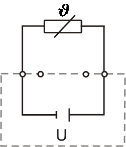
In modern evaluation devices, the resistance of the line can be compensated. Temperature fluctuations on the line, however, still influence the measurement result.
The use of a Pt1000 sensor (1000 Ohm at 0 °C) reduces the influence of the connecting cable by a factor of 10. A cable with a larger conductor cross-section also reduces the cable resistance.
3-wire connection
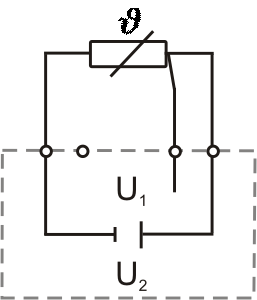
This allows the resistance of the connecting line to be determined and compensated.
The 3-wire circuit is a common connection method and offers a good compromise between cost and measurement accuracy.
4-wire connection
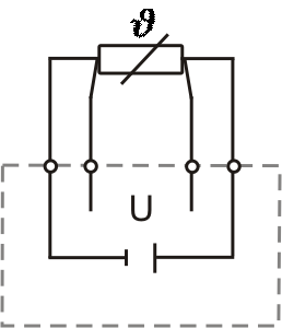
The influence of the connecting leads is thus fully compensated.
The 4-wire circuit enables the most accurate measurement, but because of the higher cost of the additional connecting leads, it is only used for special applications where high accuracy is required.
Transmitter
To avoid the problems of cable resistance, it is recommended to use a transmitter for large distances between the Pt100 sensor and the evaluation unit.This converts the resistance of the Pt100 sensors near the measuring point into a standardized 0(4)-20 mA or 0-10 Volt signal.
This signal can then be transmitted easily and cost-effectively over long distances with a 2-wire connection to the display unit.
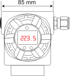
So-called "head transmitters", which are installed directly in the connection head of the Pt100 resistance thermometer, are ideal. Alternatively, a variety of devices for panel mounting are also available.
External wiring of the Pt100 resistance thermometer
- Cable
The version with cable or stranded wires is normally used for small distances between the Pt100 resistance thermometer and the evaluation unit. The cable is permanently connected to the Pt100 resistance thermometer at the factory. To keep the resistance of the cable as low as possible, the cable is normally made of copper or another highly conductive metal or metal alloy.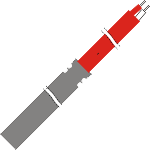
When selecting the cable, please note:- Sufficient cable cross-section to keep the resistance of the cable as low as possible
- Number of wires according to the desired connection type (2-,3-,4-wire) and number of sensors (1x Pt100, 2x Pt100)
- The cable should be sufficiently heat-resistant to withstand the sometimes high temperatures near the measuring point.
- Sufficient chemical resistance of the cable against the ambient conditions and eventually the medium
- In case of possible electromagnetic interference, a shielded cable must be used
Since the cable is mounted at the factory for these resistance sensors, the above points should be clarified in advance between the manufacturer and the user.
- Recommended cable colors for Pt100 according to DIN EN 60751 (Color code)
Recommended cable colors according to DIN EN 60751 To simplify wiring, specific cable colors are used for connecting a Pt100 sensor. Typically, red and white are used. In a 3-wire configuration, two wires are red and one is white, while in a 4-wire configuration, two wires are red and two are white. When using two Pt100 sensors, the additional colors yellow and black or grey are used for the second sensor. This color coding, which is defined according to DIN EN 60751, helps to avoid errors during installation and maintenance.


 Download table connection colors for Pt100 sensors
- Connectors
Pt100 resistance thermometers are often supplied with a wide variety of connectors with which the sensors are connected to the evaluation devices. This allows the resistance thermometers to be easily installed, replaced and securely connected. When the sensor needs to be replaced, the connector is simply disconnected without having to change the wiring.
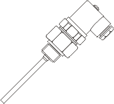
Connectors are therefore often used in confined spaces (e.g. in mechanical engineering) or when used in the laboratory with portable hand-held instruments. The connector is either mounted directly to the protective fitting of the sensor, or in the case of sensors with cable, to the cable.
The number of connector pins limits the wiring possibilities as 2-, 3- or 4-wire. It should be noted when connecting the connector that the connector pins are assigned on a manufacturer-specific basis and therefore it is not always possible to exchange them across manufacturers.
Depending on the application, there is a wide range of different connector types and manufacturers.
- Connection heads
The Pt100 resistance thermometer is supplied from the factory with a connection head. A further cable is wired in the connection head by the customer and connected to the cable of the sensor.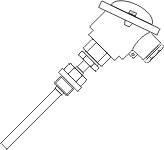
For this purpose is normaly used, a ceramic connection socket mounted in the head. Alternatively, a head transmitter can be mounted directly, which directly converts the resistance signal into a standardized output signal.
Some of the connection heads are standardized in DIN. This allows a manufacturer-independent exchange of standardized connection sockets or head transmitters.
The material specified in the DIN is cast iron, aluminum or plastic.
Examples of commercially available connectors:
Examples of commercially available connection heads
All technical articles published on pt100.de with attribution were written or reviewed by Harald Peters himself.
Author of this article:
Harald Peters – Technical author for temperature measurement technology
